Origin Story
"The Pip" - how it began... (by Andrei RW6HRM)
Many shortwave listeners are familiar with the frequencies 3756 and 5448 kHz, keeping ears listening for over 30 years. I will write some memories as a person who was in charge of this station. Please note that these memories are up to the end of the 1980s.
Until 1986, there was a "Kolos" station on the aforementioned frequencies. "Kolos" was the callsign of the North Caucasus Military District's 800th Notification Network.
It was a network of receiving devices installed in military units, military commissariats, and military factory radio rooms. Receiving devices were highly varied, ranging from professional equipment (R-154/155/250) to home receivers with shortwave bands. Because precise tuning of the network frequency was required to catch the signal, there was a transmission from the district staff notification service in Rostov-on-Don three to four times a day, and also after changing the frequency. The transmission was "I'm Kolos, I'm Kolos. Giving you counting for tuning one, two, three, ..., ten. I say again..." This was transmitted either live or from a recording.
Readiness checks for some services and communication centers were occasionally made by sending a message like the following: "I'm Kolos, I'm Kolos. Only for 815, 223 and 44. How do you read me, how do you read me?" Afterwards, the named callsigns would call back and report their reception.
Due to boredom and a lack of certainty about reception (e.g. in case of wrong tuning), one day an information service ensign suggested an enhancement: to create a marker generator which would help recipients to tune to the 800th Network's frequency. The enhancement suggested was approved, and the ensign was celebrated for his idea by being put into the "Achievement Desk of the Staff for Glory Expression." Before the change to a channel marker, the network transmitters were not active constantly, and were switched on only for transmission checks and signal transmissions. Afterwards, the transmitters were up all the time using 15 kW (Molniya transmitter) for 5448 kHz, and 1.5 kW (R-140/Vyaz transmitter) for 3756 kHz. The electricity costs and transmitter's emission were not the king's business...
The receiving radio network was reduced significantly towards the end of 1980s; some radio rooms in civilian organizations, and the military comissariat's radio centers which were responsible for all the callsigns in the area, were dismantled.
The first marker generator version was used until August 1986, and was located in the staff building. Then, while I was on practice there, I assembled the second version of the marker generator, built on a real PCB, which then began operation at the receiving site: the 72nd Communication Hub. Why at the receiving site? All major services were kept there, a shift supervisor was sitting there, while at the transmitter site there were only 3 people at best, who were responsible for the transmitter operation.
The signal from the receiving site was sent to the transmission site through channeling equipment. Multiple generators were available, so it was possible to use one from the staff, another from the receiving site (the first generator was there as well as the backup). There was also the third backup generator, which was located with the reserve communication unit in Aksai, and could have been used for both the local transmitters and the main transmitter site.
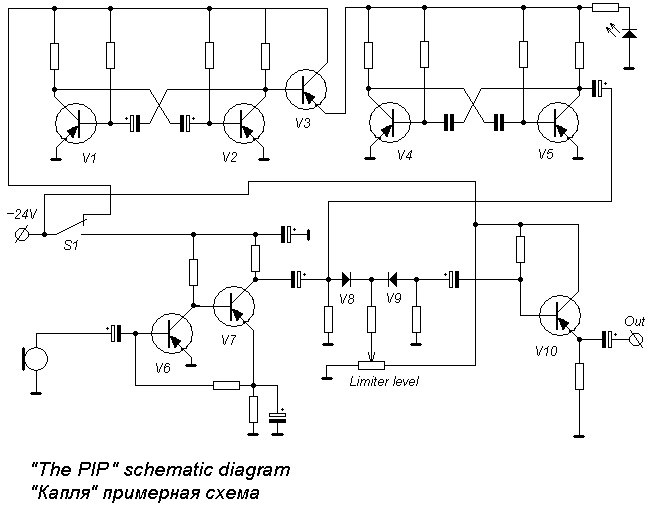
The generator diagram is simple. It contains 2 multivibrators: one slow and one sounding. The slow one has a porosity of approximately 1:3, and is assembled on transistors V1 and V2. The transistor V3 works as a power switch for the second multivibrator built on transistors V4 and V5. Both multivibrators were built by me. Also one ready-made unit from some equipment was used as a microphone amplifier (V6, V7), a limiter (V8, V9), and a buffer cascade (V10). The power voltage selected was 24 V, while the microphone model was DEMSh. All transistors are type MP42. Generator operability was indicated by two LEDs, one for power (not shown on the diagram), and another blinking in time with manipulation. Unit switching was made by using the microphone switch to send power to the diagram elements. I don't think there have been any major changes to The Pip generator; there is simply nothing to improve.